Blank Electrical Panel Schedule PDF Template
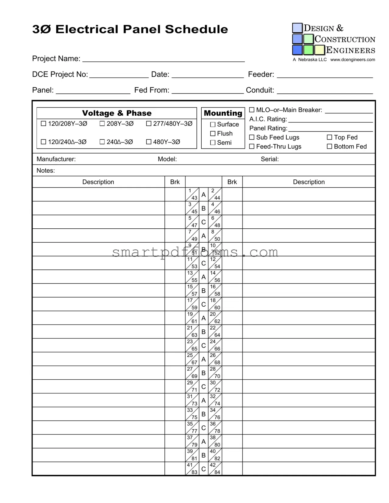
In the complex world of electrical engineering and design, the Electrical Panel Schedule form stands as a critical tool, serving multiple purposes that are essential for both the planning and execution of electrical projects. At its core, the form documents specific details about the electrical panel configuration for a project, including key information such as the project name, management by Design & Construction Engineers, and project-specific data including project numbers and dates. It meticulously records the technical specifications of the electrical panel, including feeder connections, panel identification, sources it is fed from, conduit types, voltage and phase, and the mounting method—whether it's a Main Lug Only (MLO) or contains a Main Breaker, along with the Available Interrupting Current (A.I.C.) rating. Additionally, it details the panel's physical setup such as surface or flush mounting, and the arrangement of sub-feed and feed-thru lugs. This form, set against the backdrop of specific projects managed by entities like A Nebraska LLC, as highlighted in the provided documentation, outlines not only the electrical capacities and configurations but also ensures compliance with safety standards and enhances the efficiency of project management. It itemizes the designation and description of each circuit breaker slot within the panel, marking a clear pathway for electrical engineers and construction teams to follow. Variances between three-phase (Ø) and single-phase settings, alongside the diversity in voltage requirements, reflect the form's adaptability to different project needs. Ultimately, the meticulous nature of the Electrical Panel Schedule form underscores its indispensable role in bridging the gap between detailed electrical engineering design and the practical requirements of construction and safety standards.
Preview - Electrical Panel Schedule Form
3Ø ELECTRICAL PANEL SCHEDULE |
|
|
|
DESIGN & |
||||
|
|
|
|
CONSTRUCTION |
||||
|
|
|
|
|
|
|||
|
|
|
|
|
|
|
|
ENGINEERS |
|
|
|
|
|
|
|
|
|
Project Name: |
|
|
A Nebraska LLC www.dcengineers.com |
|||||
DCE Project No: |
|
Date: |
|
|
|
|
Feeder: |
|
Panel: |
|
Fed From: |
|
|
|
|
Conduit: |
|
Voltage & Phase |
|
Mounting |
|
|||||
|
A.I.C. Rating: |
|
||||||
|
|
Surface |
|
|||||
|
|
Panel Rating: |
|
|||||
|
|
|
|
|
|
Flush |
|
|
|
|
|
|
|
|
Sub Feed Lugs |
Top Fed |
|
120/240 |
240 |
|
|
|
Semi |
|||
|
|
|
Bottom Fed |
|||||
|
|
|
|
|
|
|
||
Manufacturer: |
|
Model: |
|
|
|
|
Serial: |
|
Notes: |
|
|
|
|
|
|
|
|
Description |
Brk |
|
|
|
Brk |
Description |
|
|
|
|
1 |
43 |
A |
2 |
44 |
|
|
|
|
3 |
45 |
B |
4 |
46 |
|
|
|
|
5 |
47 |
C |
6 |
48 |
|
|
|
|
7 |
49 |
A |
8 |
50 |
|
|
|
|
9 |
|
B |
10 |
|
|
|
|
|
|
51 |
|
52 |
|
|
|
|
|
11 |
C |
12 |
|
|
||
|
|
|
53 |
|
54 |
|
|
|
|
|
13 |
A |
14 |
|
|
||
|
|
|
55 |
|
56 |
|
|
|
|
|
15 |
B |
16 |
|
|
||
|
|
|
57 |
|
58 |
|
|
|
|
|
17 |
C |
18 |
|
|
||
|
|
|
59 |
|
60 |
|
|
|
|
|
19 |
A |
20 |
|
|
||
|
|
|
61 |
|
62 |
|
|
|
|
|
21 |
B |
22 |
|
|
||
|
|
|
63 |
|
64 |
|
|
|
|
|
23 |
C |
24 |
|
|
||
|
|
|
65 |
|
66 |
|
|
|
|
|
25 |
A |
26 |
|
|
||
|
|
|
67 |
|
68 |
|
|
|
|
|
27 |
B |
28 |
|
|
||
|
|
|
69 |
|
70 |
|
|
|
|
|
29 |
C |
30 |
|
|
||
|
|
|
71 |
|
72 |
|
|
|
|
|
31 |
A |
32 |
|
|
||
|
|
|
73 |
|
74 |
|
|
|
|
|
33 |
B |
34 |
|
|
||
|
|
|
75 |
|
76 |
|
|
|
|
|
35 |
C |
36 |
|
|
||
|
|
|
77 |
|
78 |
|
|
|
|
|
37 |
A |
38 |
|
|
||
|
|
|
79 |
|
80 |
|
|
|
|
|
39 |
B |
40 |
|
|
||
|
|
|
81 |
|
82 |
|
|
|
|
|
41 |
C |
42 |
|
|
||
|
|
|
83 |
|
84 |
|
|
|

1Ø ELECTRICAL PANEL SCHEDULE |
|
|
DESIGN & |
|||||
|
|
|
CONSTRUCTION |
|||||
|
|
|
|
|
|
|||
|
|
|
|
|
|
|
|
ENGINEERS |
|
|
|
|
|
|
|
|
|
Project Name: |
|
|
A Nebraska LLC www.dcengineers.com |
|||||
DCE Project No: |
Date: |
|
|
|
|
Feeder: |
|
|
Panel: |
|
Fed From: |
|
|
|
|
Conduit: |
|
|
Voltage & Phase |
|
Mounting |
|
||||
|
|
A.I.C. Rating: |
|
|||||
|
|
|
Surface |
|
||||
|
|
|
Panel Rating: |
|
||||
|
|
|
Flush |
|
||||
|
|
|
Sub Feed Lugs |
Top Fed |
||||
|
|
|
|
Semi |
||||
|
|
|
|
Bottom Fed |
||||
|
|
|
|
|
|
|
||
Manufacturer: |
|
Model: |
|
|
|
|
Serial: |
|
Notes: |
|
|
|
|
|
|
|
|
|
Description |
Brk |
|
|
|
Brk |
Description |
|
|
|
1 |
43 |
A |
2 |
44 |
|
|
|
|
3 |
45 |
B |
4 |
46 |
|
|
|
|
5 |
47 |
A |
6 |
48 |
|
|
|
|
7 |
49 |
B |
8 |
50 |
|
|
|
|
9 |
|
A |
10 |
|
|
|
|
|
|
51 |
|
52 |
|
|
|
|
|
11 |
B |
12 |
|
|
||
|
|
|
53 |
|
54 |
|
|
|
|
|
13 |
A |
14 |
|
|
||
|
|
|
55 |
|
56 |
|
|
|
|
|
15 |
B |
16 |
|
|
||
|
|
|
57 |
|
58 |
|
|
|
|
|
17 |
A |
18 |
|
|
||
|
|
|
59 |
|
60 |
|
|
|
|
|
19 |
B |
20 |
|
|
||
|
|
|
61 |
|
62 |
|
|
|
|
|
21 |
A |
22 |
|
|
||
|
|
|
63 |
|
64 |
|
|
|
|
|
23 |
B |
24 |
|
|
||
|
|
|
65 |
|
66 |
|
|
|
|
|
25 |
A |
26 |
|
|
||
|
|
|
67 |
|
68 |
|
|
|
|
|
27 |
B |
28 |
|
|
||
|
|
|
69 |
|
70 |
|
|
|
|
|
29 |
A |
30 |
|
|
||
|
|
|
71 |
|
72 |
|
|
|
|
|
31 |
B |
32 |
|
|
||
|
|
|
73 |
|
74 |
|
|
|
|
|
33 |
A |
34 |
|
|
||
|
|
|
75 |
|
76 |
|
|
|
|
|
35 |
B |
36 |
|
|
||
|
|
|
77 |
|
78 |
|
|
|
|
|
37 |
A |
38 |
|
|
||
|
|
|
79 |
|
80 |
|
|
|
|
|
39 |
B |
40 |
|
|
||
|
|
|
81 |
|
82 |
|
|
|
|
|
41 |
A |
42 |
|
|
||
|
|
|
83 |
|
84 |
|
|
|
Form Data
| Fact Name | Description |
|---|---|
| Project Identification | The form is being used for a project named A Nebraska LLC, managed by Design & Construction Engineers (DCE). |
| Project Number & Website | Each form includes a specific DCE Project Number and refers to the company's website (www.dcengineers.com). |
| Date and Feeder Information | The form records vital project details such as the date of issue and feeder specifics. |
| Panel and Power Characteristics | Details about the panel (including Fed From and Conduit), Voltage & Phase Mounting information are specified. |
| A.I.C. Rating and Panel Rating | The A.I.C. (Ampere Interrupting Capacity) Rating is provided along with 120/208Y–3Ø, 277/480Y–3Ø, among others, and panel rating details including mounting options. |
| Manufacturer and Model Information | Information about the panel's manufacturer, model, and serial number is provided for identification and reference. |
| Governing Laws | While the form is specific to a project that may be located in Nebraska, actual governing laws were not specified. Always consult the local building codes and regulations for electrical installations. |
Instructions on Utilizing Electrical Panel Schedule
When planning for electrical installations or updates, accurately completing an Electrical Panel Schedule form is a crucial step for engineers and electricians. This document details the organization and capacity of a building's electrical panel, ensuring that the electrical system is both efficient and up to code. The following steps provide a clear guide for filling out this form, covering both three-phase (3Ø) and single-phase (1Ø) electrical panel schedules. Proper completion aids in the effective management and documentation of a project's electrical infrastructure.
- Start by entering the project's formal name in the "Project Name" section.
- Proceed to include the project's unique identifier or number given by Design & Construction Engineers (DCE) in the "DCE Project No" field.
- Record the current date in the designated "Date" space.
- Specify the feeder's characteristics in the "Feeder" section, detailing its origin or source.
- In the "Panel" area, mark down the specific panel being scheduled.
- Detail the panel's source in "Fed From," indicating where the power is coming from.
- Under "Conduit," note the type and size of the conduit used.
- Select the appropriate voltage and phase for your project, marking the corresponding box. This includes options such as 120/208Y–3Ø for three-phase systems and 120–1Ø for single-phase systems.
- Choose the correct mounting option, whether it’s Surface, Flush, or other, and indicate if the panel uses an MLO (Main Lug Only) or has a Main Breaker.
- Input the A.I.C. (Ampere Interrupting Capacity) Rating as per the panel's specification.
- Specify the "Panel Rating," marking the suitable option based on the installation's characteristics.
- Select if the installation uses Sub Feed Lugs or Feed-Thru Lugs, and whether it is Top Fed or Bottom Fed.
- Manufacturer, model, and serial number of the electrical panel must be entered respectively in the "Manufacturer," "Model," and "Serial" fields.
- In the "Notes" section, record any additional information pertinent to the electrical panel or installation.
- For each circuit, fill in the "Description," "Brk" (Breaker Size), and "Brk Description" fields. This involves noting the specific uses, capacities, and any special details for circuits numbered 1 through 84, as per the panel's configuration.
After completing these steps, review the form to ensure all entered information is accurate and comprehensive. This document serves as a vital tool in both the construction and maintenance of the property's electrical system, laying out clear, accessible data for all parties involved. Properly documenting this information not only facilitates smoother operations but also helps in adhering to safety standards and regulatory compliance.
Obtain Answers on Electrical Panel Schedule
-
What is an Electrical Panel Schedule?
An Electrical Panel Schedule is a detailed document that outlines all the circuit connections in an electrical panel. It includes information on the project, such as the name and details provided by the engineering firm, in this case, Design & Construction Engineers (DCE). It lists the circuits, their descriptions, breaker numbers, and applicable notes, making it essential for installation, maintenance, and troubleshooting electrical systems.
-
Why are there different voltage and phase listings?
The Electrical Panel Schedule can accommodate various electrical systems, indicating it supports multiple voltage and phase configurations. For instance, configurations such as 120/208Y–3Ø and 277/480Y–3Ø for three-phase systems, alongside single-phase options like 120/208–1Ø and 120/240–1Ø. This diversity ensures the schedule can adapt to different electrical setups, from residential to commercial and industrial environments.
-
What does "Fed From" mean?
"Fed From" refers to the power source or upstream connection that supplies electricity to the panel. This could be a transformer, another panel, or a utility service. It provides essential details for understanding the panel's place within the electrical distribution system and aids in tracing the flow of electricity for management or fault diagnosis.
-
How is the mounting type significant?
The mounting type, whether surface, flush, or semi, indicates how the panel is installed in relation to the surrounding structure. Surface-mounted panels attach directly to the wall, while flush-mounted panels are inset, providing a more integrated look. Semi mounting might refer to a compromise between the two or a specialized mounting method. This information is crucial for planning the physical layout of electrical installations.
-
What is A.I.C. Rating?
A.I.C. Rating stands for "Ampere Interrupting Capacity." It measures the maximum current an electrical device can interrupt without damage. Knowing the A.I.C. Rating of a panel is vital for ensuring the safety and durability of the electrical system, particularly in conditions where short circuits or overloads may occur.
-
Can you explain the significance of Sub Feed Lugs and Feed-Thru Lugs?
Sub Feed Lugs and Feed-Thru Lugs are types of connections found in electrical panels. Sub Feed Lugs allow for the downstream connection of additional panels without occupying space on the main busbar. Feed-Thru Lugs enable the panel to feed power to another panel while still powering its own circuits. These options offer flexibility in expanding or distributing electrical systems.
-
What does the list of "Brk Description" represent?
The "Brk Description" column gives details about each circuit breaker in the panel, including its type labeled with letters (e.g., A, B, C) and its position number. This information helps in identifying the purpose of each circuit and in organizing the panel for easy operation and maintenance.
-
Why is the manufacturer information included?
Including the manufacturer, model, and serial number is critical for various reasons. It ensures compatibility of components, makes ordering replacements easier, and assists in troubleshooting specific equipment issues. Furthermore, warranty claims or recalls often require this information, making it vital for the efficient management of electrical panels.
Common mistakes
Not specifying the voltage and phase: People often overlook filling in the voltage and phase, crucial for understanding the electrical capacity and requirements of the panel. The options include 120/208Y–3Ø, 208Y–3Ø, 277/480Y–3Ø for three-phase systems and 120/208–1Ø, 120–1Ø, 277/480–1Ø for single-phase systems. Each configuration supports different load types and must be correctly indicated to ensure compatibility with the connected circuits.
Incorrectly identifying panel location options: The form provides options for mounting, such as Surface, Flush, and whether the panel is Top Fed or Bottom Fed with possibilities for Sub Feed Lugs or Semi Feed-Thru Lugs. Incorrectly identifying these specifications can lead to improper installation environments and safety hazards, as each type of mounting and feeding has its own set of requirements and considerations for accessibility and wiring.
Leaving the Manufacturer, Model, and Serial fields blank: Each panel has unique characteristics and specifications tied to its Manufacturer, Model, and Serial Number. Omitting this information can prevent proper identification for future maintenance, replacement, or warranty claims. It's imperative to record this data to ensure accurate identification and compatibility of replacement parts or in the event of troubleshooting.
Mislabeling Circuit Breaker positions and descriptions: The form contains fields for circuit breaker positions labeled from 1 to 84, with additional spaces for description and type (A, B, C for three-phase; A, B for single-phase). Mixing up these labels or descriptions can cause confusion and potential danger during maintenance or when modifications are made to the electrical system, as it's essential to accurately describe the load or area each circuit supports.
Ignoring the Notes section: Many users fill out the required technical specifications but neglect the Notes section at the bottom of the form. This area is critical for providing additional information, unique considerations, or specific instructions related to the electrical panel schedule. Relevant details might include special handling instructions, safety concerns, or future expansion considerations. Failing to utilize this section can result in lost information that is pertinent for those interacting with the electrical panel in the future.
When completing an Electrical Panel Schedule form, attention to detail and thoroughness are paramount. Even minor mistakes or omissions can have significant implications. By carefully addressing each field, users can ensure the safety, functionality, and maintainability of their electrical systems.
Documents used along the form
When working on electrical installations or maintenance, an Electrical Panel Schedule form is a crucial document. It helps in identifying the layout and capacities of a building's electrical panels, which is essential for safe and effective electrical work. In addition to the Electrical Panel Schedule, there are several other documents and forms that often accompany it to ensure a comprehensive overview and management of the electrical systems. These documents support various stages of electrical design, installation, and maintenance projects.
- Electrical Load Calculation Worksheet: This document is used to calculate the total electrical load of a building or specified area before determining the appropriate size and type of electrical panel needed. It takes into account all the electrical devices and fixtures that will draw power from the panel.
- Electrical Permit Application: Before any electrical work can begin, a permit must usually be obtained from the local building department or authority having jurisdiction (AHJ). This form is filled out with the project details and submitted for approval, ensuring that the planned work meets local codes and standards.
- Circuit Directory: Similar to the panel schedule, a Circuit Directory provides a detailed map of what each circuit breaker controls but is often more detailed about specific outlets, fixtures, or appliances served. This is essential for troubleshooting and future maintenance.
- Inspection Checklist for Electrical Systems: After installation, an inspection checklist is used to verify that all components of the electrical system adhere to safety standards and regulations. It covers wiring methods, grounding, panel installation, and more, ensuring a thorough review.
- As-Built Electrical Drawings: These are detailed drawings created after the completion of a project, reflecting all changes made during construction. As-built drawings provide a final, accurate record of the electrical system and are crucial for future modifications or maintenance work.
These documents, when used alongside the Electrical Panel Schedule, form a complete package for managing electrical projects efficiently and safely. Each serves a unique purpose, from planning and permitting through installation and inspection, to ensure that all electrical work is up to code, effectively designed, and documented for future reference. Understanding and utilizing these documents properly can help avoid costly mistakes and ensure a safe, efficient electrical system.
Similar forms
Blueprints or Construction Drawings: Similar to electrical panel schedules, blueprints provide detailed information about the design and specifics of a project. They are both essential in the planning phase of construction, offering visual representations of what needs to be built or installed. Where blueprints focus on the overall layout and design, electrical panel schedules deal specifically with the organization and specifics of electrical panels.
Material Lists: Material lists enumerate items that are required for a project, including quantities and specifications, much like an electrical panel schedule lists circuit breakers, their positions, and details regarding the electrical panel's characteristics. Both are crucial for procurement and ensuring that the right materials and components are available when needed.
Equipment Schedules: Equipment schedules, used in various types of engineering projects, outline the specifics of each piece of equipment, including its size, capacity, and location. This document is closely aligned with electrical panel schedules, which detail the components within the electrical panel, their configurations, and specific electrical parameters.
Maintenance Schedules: Maintenance schedules specify when and what kind of maintenance tasks are to be performed on machinery or equipment to ensure its optimal operation. By comparison, electrical panel schedules provide necessary details for the maintenance and inspection of electrical panels, by detailing the setup and making recommendations for its proper upkeep.
Operation Manuals: Those are comprehensive guides to the functioning and handling of equipment or systems. Electrical panel schedules supplement operation manuals by providing detailed charts and data specifically for the configuration and maintenance of electrical panels, helping users understand the arrangement and capacity of their electrical systems.
Dos and Don'ts
When filling out an Electrical Panel Schedule form, it is critical to ensure accuracy and completeness for the safe and efficient operation of electrical systems. The following lists provide guidance on what you should and should not do during this process.
What You Should Do
- Double-check all information: Before you submit, verify each detail against your project documentation to ensure accuracy.
- Use clear, legible handwriting or type: If the form is filled out by hand, write neatly to avoid any misunderstandings. Better yet, if possible, fill it out digitally.
- Consult the project's electrical diagrams: This helps in ensuring that the information about circuits, breakers, and the panel aligns with the overall electrical plan.
- Include detailed notes: Any specifics that can impact the electrical configuration, such as future expansion or particular load requirements, should be clearly noted.
What You Shouldn't Do
- Rush through the form: Taking your time to fill out each section carefully can prevent costly mistakes and rework.
- Leave sections blank: If a section applies to your project, make sure to include the information. Leaving fields blank can lead to oversights and operational issues.
- Assume details are obvious: Do not rely on others’ familiarity with the project. Explicitly state all relevant information, even if it seems evident to you.
- Forget to review manufacturer info: Incorrect data about the manufacturer, model, or serial number can lead to compatibility issues or problems in ordering replacements.
Misconceptions
When it comes to Electrical Panel Schedules, several misconceptions may lead to confusion or errors during their interpretation or creation. Below are seven common misunderstandings and clarifications to ensure accurate handling and documentation.
- All Electrical Panel Schedules are identical: The reality is that schedules can significantly vary depending on the project's specifications, including the type of electrical system (e.g., 3Ø or 1Ø), the voltage and phase requirements, and the physical configuration of the panel (e.g., surface or flush mounting).
- Only electricians need to understand them: While electricians are the primary users, project managers, engineers, and safety inspectors also utilize these schedules to ensure the electrical system's design, installation, and maintenance align with standards and project requirements.
- The A.I.C. Rating is not crucial: The A.I.C. (Ampere Interrupting Capacity) Rating is essential for ensuring that the panel and the circuit breakers can handle the maximum possible fault currents safely. Overlooking this aspect can lead to safety hazards.
- Listing of every breaker is always complete: In some instances, the initial schedule may not list all breakers, especially in a project's early phases or when future expansions are anticipated. Subsequent updates are common to incorporate changes or additional circuits.
- Panel schedules are only for new installations: Both new installations and existing systems undergoing inspection, maintenance, or upgrades require accurate and up-to-date panel schedules. These documents serve as a guide for modifications and ensure compliance with electrical codes.
- The 'Fed From' section is insignificant: Understanding where the panel receives its power from ('Fed From') is vital for tracing system layouts, especially during troubleshooting or system expansions. This information ensures that personnel understand the power source and distribution logistics.
- Description fields are optional: The 'Description' sections for each breaker are critical for identifying the circuit's purpose and location quickly. These details facilitate faster decision-making, especially during emergencies or when performing maintenance.
Correcting these misconceptions enhances safety, compliance, and efficiency in handling electrical panel schedules. It ensures that all team members, regardless of their role, comprehend the electrical system’s design and operational specifics accurately.
Key takeaways
Filling out and using an Electrical Panel Schedule form is a fundamental task for accurately managing and documenting the configuration of electrical panels in any construction or renovation project. Understanding how to properly complete this form can help ensure electrical systems are safe, efficient, and compliant with regulations. Here are seven key takeaways to assist in this process:
- Project Information is Crucial: Always start by filling in the complete project information, including the project name, project number, and the details of the engineering firm overseeing the project. This information helps in identifying the specific panel schedule in the broader context of the project.
- Detailed Panel Identification: The form requires specific details about the panel, such as the feeder size, panel designation, and where it is fed from. This is vital for understanding the electrical circuit's layout and ensuring that the correct panel is being worked on or inspected.
- Voltage and Phase Classification: Accurately indicating the voltage and phase is essential for the safety and proper functioning of the electrical system. Different equipment may have varying voltage and phase requirements, affecting how they are connected to the panel.
- Installation Details Matter: Whether the panel is surface mounted, flush mounted, has sub feed lugs, or is top or bottom fed, these installation specifics influence both the physical fit of the panel and its accessibility for maintenance or expansion.
- Manufacturer Data: Recording the manufacturer, model, and serial number of the panel provides essential information for maintenance, warranty claims, and for ordering replacement parts or accessories.
- Understanding Circuit Designations: The form lists circuit numbers with associated breaker sizes and descriptions. Accurately filling out these sections supports troubleshooting efforts, future modifications, and ensures a clear understanding of what circuits are feeding.
- Notes are Your Friend: Use the notes section liberally to mark any peculiarities, customization, or specific instructions about the electrical panel. This can include safety warnings, specific testing results, or custom configurations that don’t fit elsewhere on the form.
Properly filling out and maintaining an Electrical Panel Schedule is not just about administrative accuracy; it’s about ensuring the safety and efficiency of electrical systems in buildings. Attention to detail in this process supports professionals in making informed decisions about electrical load management, maintenance, and system expansions or modifications.
Popular PDF Forms
How to Create a Professional Resume - Include the job title, company name, and address for each position to give clear context to your work history.
Medication Reconciliation Process - Includes an option for noting difficulties in obtaining medication information, ensuring comprehensive care.
Rental Application Form Maryland - By detailing the immediate steps following application approval, including lease signing and initial payments, expectations are set clearly for both parties.