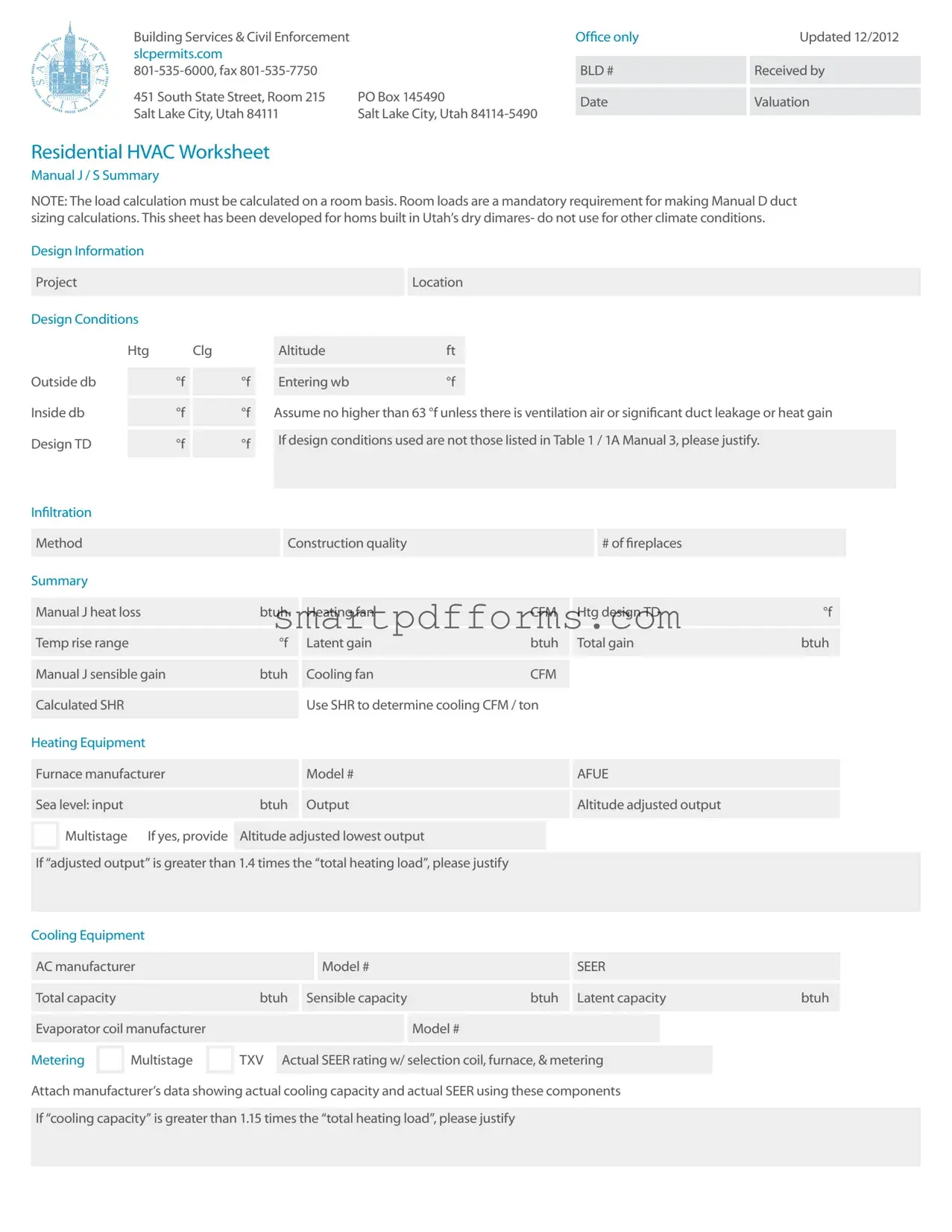
Blank Manual J PDF Template
At the heart of residential heating, ventilation, and air conditioning (HVAC) system design lies the seemingly innocuous Manual J form. Developed to cater to homes in Utah’s arid climate, this comprehensive worksheet plays a pivotal role in ensuring that HVAC systems are tailored to specific home layouts and environmental conditions. The precise calculation of room-by-room loads, as mandated by the form, sets the groundwork for the critical Manual D duct sizing. Beyond mere numbers, the Manual J form encapsulates a range of design conditions, including altitude adjustments and the balancing act between inside and outside temperatures, to refine the specification of both heating and cooling equipment. Infiltration methods, tied to construction quality and fireplace presence, further detail the home's heat gain and loss dynamics. Heat loss and sensible gain computations feed directly into equipment selection, marrying efficiency ratings with calculated needs. Evaporative and cooling contributions, alongside ductwork considerations, round out this essential tool. Far from being a static document, the Manual J form adjusts for altitude, acknowledges multistage equipment, and demands justification for deviations, ensuring that every HVAC system it influences is as efficient and tailored to the project as possible. With mandatory fields spanning project specifics to intricate design considerations, it stands as a testament to thorough preparation meeting skilled execution in the realm of HVAC design and implementation.
Preview - Manual J Form

Building Services & Civil Enforcement slcpermits.com
451 South State Street, Room 215 |
PO Box 145490 |
Salt Lake City, Utah 84111 |
Salt Lake City, Utah |
Office only |
Updated 12/2012 |
BLD #  Received by
Date  Valuation
Residential HVAC Worksheet
Manual J / S Summary
NOTE: The load calculation must be calculated on a room basis. Room loads are a mandatory requirement for making Manual D duct sizing calculations. This sheet has been developed for homs built in Utah’s dry dimares- do not use for other climate conditions.
Design Information |
|
|
|
|
|
|
|
|
|
|
|
|
|
|
|
|
|
|
|
|
|
|
|
|
|
|||||
|
|
|
|
|
|
|
|
|
|
|
|
|
|
|
|
|
|
|
|
|
|
|
|
|
|
|
|
|
|
|
|
Project |
|
|
|
|
|
|
|
|
|
|
|
|
|
|
Location |
|
|
|
|
|
|
|
|
|
|
|
|||
|
|
|
|
|
|
|
|
|
|
|
|
|
|
|
|
|
|
|
|
|
|
|
|
|
|
|
|
|
|
|
Design Conditions |
|
|
|
|
|
|
|
|
|
|
|
|
|
|
|
|
|
|
|
|
|
|
|
|
|
|||||
|
|
|
|
|
|
|
|
|
|
|
|
|
|
|
|
|
|
|
|
|
|
|
|
|
|
|
|
|
||
|
|
Htg |
Clg |
|
|
Altitude |
|
|
ft |
|
|
|
|
|
|
|
|
|
|
|
|
|
||||||||
|
|
|
|
|
|
|
|
|
|
|
|
|
|
|
|
|
|
|
|
|
|
|
|
|
|
|
|
|
|
|
|
|
|
|
|
|
|
|
|
|
|
|
|
|
|
|
|
|
|
|
|
|
|
|
|
|
|
|
|||
Outside db |
|
|
°f |
|
|
°f |
|
Entering wb |
|
|
°f |
|
|
|
|
|
|
|
|
|
|
|
|
|
||||||
|
|
|
|
|
|
|
|
|
|
|
|
|
|
|
|
|
|
|
|
|
|
|
|
|
|
|
|
|
||
|
|
|
|
|
|
|
|
|
|
|
|
|
|
|
|
|
||||||||||||||
Inside db |
|
|
°f |
|
|
°f |
|
Assume no higher than 63 °f unless there is ventilation air or significant duct leakage or heat gain |
||||||||||||||||||||||
|
|
|
|
|
|
|
|
|
|
|
|
|
|
|
|
|
|
|
|
|
|
|
|
|
|
|
|
|||
|
|
|
|
|
|
|
|
|
|
|
|
|
|
|
|
|
|
|
|
|
|
|
|
|
|
|
|
|
|
|
Design TD |
|
|
°f |
|
|
°f |
|
If design conditions used are not those listed in Table 1 / 1A Manual 3, please justify. |
|
|
|
|
||||||||||||||||||
|
|
|
|
|
|
|
|
|
|
|
|
|
|
|
|
|
|
|
|
|
|
|
|
|
|
|
||||
|
|
|
|
|
|
|
|
|
|
|
|
|
|
|
|
|
|
|
|
|
|
|
|
|
|
|
|
|
|
|
Infiltration |
|
|
|
|
|
|
|
|
|
|
|
|
|
|
|
|
|
|
|
|
|
|
|
|
|
|
|
|
|
|
|
|
|
|
|
|
|
|
|
|
|
|
|
|
|
|
|
|
|
|
|
|
|
|
|
|
|
|
|
||
|
|
|
|
|
|
|
|
|
|
|
|
|
|
|
|
|
|
|
|
|
|
|
|
|
|
|
|
|
|
|
|
Method |
|
|
|
|
|
|
|
|
Construction quality |
|
|
|
|
|
|
|
|
# of fireplaces |
|
|
|
|
|
||||||
|
|
|
|
|
|
|
|
|
|
|
|
|
|
|
|
|
|
|
|
|
|
|
|
|
|
|
|
|
|
|
Summary |
|
|
|
|
|
|
|
|
|
|
|
|
|
|
|
|
|
|
|
|
|
|
|
|
|
|
|
|
|
|
|
|
|
|
|
|
|
|
|
|
|
|
|
|
|
|
|
|
|
|
|
|
|
|
|
|
|
||||
|
Manual J heat loss |
|
|
|
|
btuh |
|
Heating fan |
|
|
|
|
CFM |
|
Htg design TD |
|
°f |
|
|
|
||||||||||
|
|
|
|
|
|
|
|
|
|
|
|
|
|
|
|
|
|
|
|
|
|
|
|
|
|
|
|
|||
|
|
|
|
|
|
|
|
|
|
|
|
|
|
|
|
|
|
|
|
|
|
|
|
|
|
|
|
|||
|
Temp rise range |
|
|
|
|
to |
|
|
°f |
|
Latent gain |
|
|
|
|
btuh |
|
Total gain |
|
|
btuh |
|
|
|
||||||
|
|
|
|
|
|
|
|
|
|
|
|
|
|
|
|
|
|
|
|
|
|
|
|
|
|
|
|
|
||
|
|
|
|
|
|
|
|
|
|
|
|
|
|
|
|
|
|
|
|
|
|
|
|
|
|
|
|
|
||
|
Manual J sensible gain |
|
|
|
btuh |
|
Cooling fan |
|
|
|
|
CFM |
|
|
|
|
|
|
|
|
|
|
||||||||
|
|
|
|
|
|
|
|
|
|
|
|
|
|
|
|
|
|
|
|
|
|
|
|
|
|
|
|
|
|
|
|
|
|
|
|
|
|
|
|
|
|
|
Use SHR to determine cooling CFM / ton |
|
|
|
|
|
|
|
|
|
|
||||||||
|
Calculated SHR |
|
|
|
|
|
|
|
|
|
|
|
|
|
|
|
|
|
|
|
|
|||||||||
|
|
|
|
|
|
|
|
|
|
|
|
|
|
|
|
|
|
|
|
|
|
|
|
|
|
|
|
|
|
|
Heating Equipment |
|
|
|
|
|
|
|
|
|
|
|
|
|
|
|
|
|
|
|
|
|
|
|
|
|
|||||
|
|
|
|
|
|
|
|
|
|
|
|
|
|
|
|
|
|
|
|
|
|
|
|
|
|
|
|
|||
|
Furnace manufacturer |
|
|
|
|
|
|
|
Model # |
|
|
|
|
|
|
|
AFUE |
|
|
|
|
|
|
|||||||
|
|
|
|
|
|
|
|
|
|
|
|
|
|
|
|
|
|
|
|
|
|
|
|
|
|
|
|
|||
|
|
|
|
|
|
|
|
|
|
|
|
|
|
|
|
|
|
|
|
|
|
|
|
|
|
|
|
|||
|
Sea level: input |
|
|
|
|
|
|
btuh |
|
Output |
|
|
|
|
|
|
|
Altitude adjusted output |
|
|
|
|
||||||||
|
|
|
|
|
|
|
|
|
|
|
|
|
|
|
|
|
|
|
|
|
|
|
|
|
|
|
|
|||
|
Multistage |
|
If yes, provide |
|
|
|
|
|
|
|
|
|
|
|
|
|
|
|
|
|
|
|
||||||||
|
|
Altitude adjusted lowest output |
|
|
|
|
|
|
|
|
|
|
|
|
|
|||||||||||||||
|
|
|
|
|
|
|
|
|
|
|
|
|
|
|
|
|
|
|
|
|
|
|
|
|
|
|||||
|
|
|
|
|
|
|
|
|
|
|
|
|
|
|
|
|
|
|
|
|
|
|
|
|
||||||
|
If “adjusted output” is greater than 1.4 times the “total heating load”, please justify |
|
|
|
|
|
|
|
|
|
|
|||||||||||||||||||
|
|
|
|
|
|
|
|
|
|
|
|
|
|
|
|
|
|
|
|
|
|
|
|
|
|
|
|
|
|
|
Cooling Equipment |
|
|
|
|
|
|
|
|
|
|
|
|
|
|
|
|
|
|
|
|
|
|
|
|
|
|||||
|
|
|
|
|
|
|
|
|
|
|
|
|
|
|
|
|
|
|
|
|
|
|
|
|
|
|
|
|||
|
AC manufacturer |
|
|
|
|
|
|
|
|
|
Model # |
|
|
|
|
|
|
|
SEER |
|
|
|
|
|
|
|||||
|
|
|
|
|
|
|
|
|
|
|
|
|
|
|
|
|
|
|
|
|
|
|
|
|
|
|
||||
|
|
|
|
|
|
|
|
|
|
|
|
|
|
|
|
|
|
|
|
|
|
|
|
|
||||||
|
Total capacity |
|
|
|
|
|
|
btuh |
|
Sensible capacity |
|
|
|
btuh |
|
Latent capacity |
|
btuh |
|
|
|
|||||||||
|
|
|
|
|
|
|
|
|
|
|
|
|
|
|
|
|
|
|
|
|
|
|
|
|
|
|
|
|||
|
|
|
|
|
|
|
|
|
|
|
|
|
|
|
|
|
|
|
|
|
|
|
|
|
|
|
|
|||
|
Evaporator coil manufacturer |
|
|
|
|
|
|
|
|
|
Model # |
|
|
|
|
|
|
|
|
|
|
|
||||||||
|
|
|
|
|
|
|
|
|
|
|
|
|
|
|
|
|
|
|
||||||||||||
|
|
Multistage |
|
TXV |
|
|
|
|
|
|
|
|
|
|
|
|
|
|
|
|
|
|
|
|
|
|
||||
Metering |
|
Actual SEER rating w/ selection coil, furnace, & metering |
|
|
|
|
|
|
||||||||||||||||||||||
|
|
|
|
|
|
|
|
|
|
|
|
|
|
|
|
|
|
|
|
|
|
|
|
|
|
|
|
|
|
|
Attach manufacturer’s data showing actual cooling capacity and actual SEER using these components
If “cooling capacity” is greater than 1.15 times the “total heating load”, please justify
Manual J / S Summary
Instructions
The load information asked for on the summary must be taken from the actual load calculation completed on the project.
Project
Identify project name, lot number- information that matches the plan submitted.
Location
The city or town must be reasonably close to actual location. Software used may not have the specific location in the database.
Outside Dry Bulb, Inside Dry Bulb
Temperature data should be from Table 1 or Table 1A of ACCA Manual J. It is understood that there may be situations where a slight adjustment to this values is necessary. For example; there may be areas in the Salt Lake Valley where the low temperature is historically lower than the airport temperature. If values are adjusted- please justify the adjustment. Provide both heating (htg) and cooling (clg) design temperatures. If inside
or outside design conditions listed are not the same values listed in Manual J, explain why the different values were used.
Entering WB
The entering
63 °f (75 °f dry bulb) relative humidity). A higher wb temperature will result from duct leakage,
air temperature. Use this wb temperature when selecting cooling condenser from manufacturer’s comprehensive data.
Design TD
TD: the temperature difference between inside and outside design temperatures.
Infiltration
Infiltration calculations are based on the Construction Quality. Version 7 of Manual ] uses Best, Average or Poor to evaluate Infiltration. Version 8AE uses Tight,
not be counted. Methods include: Simplified
/Default Method- taken from Table 5A; Component Leakage Area Method- calculating infiltration based on individual leakage points taken from Table 5C of Manual J8; or Blower Door Method, where the actual leakage is based on a blower door test on the home.
Manual J Heat Loss
This is the whole house winter heat loss taken directly from the completed attached Load Calculation. Load must account for all factors such as loss building components as well as loss through infiltration, ventilation, and duct losses.
Heating Fan
Heating airflow typically may be lower than cooling cfm. Adjusted to insure the temperature rise across the heat exchanger falls within the range specified by the manufacturer. Software will often do this calculation and provide a correct heating cfm. See Manual S Section
Manufacturer’s Temperature Rise Range
Range taken from manufacturer’s performance data. Various manufacturers may certify ranges from 20 - 70 °f.
Manual J — Sensible Gain
The whole house summer heat gain taken directly from the completed attached Load Calculation. Load must account for all factors including gain through building components, solar gain, infiltration, ventilation and ducts. Also includes the sensible internal gains from appliances and people.
Manual 3 — Latent Gain
The gains due to moisture in the air. Large latent load are typically from moisture migration into the home from outside in humid climates. People, cooking, plants, bathing and laundry washing can all add to the latent load in a home.
Total Gain
The combined total of the sensible and latent gain. May be referred to as Total Cooling Load.
SHR- Sensible Heat Ratio
Use to determine Cooling cfm per ton. The ratio of sensible heat gain to total heat gain. SHR = Sensible Heat Gain ÷ Total Heat Gain. Recommended air flows: If SHR is below 0.80 select 350 cfm / ton; if SHR is between 0.80 & 0.85 select 400 cfm; if SHR is greater than 0.85, select 450 cfm
/ton. Note: This cfm is not the final cfm; additional adjustment may be required for Altitude. See next item- Cooling Fan.
Cooling Fan
Software used to perform the calculation will typically provide a minimum cfm based on the minimum required size of the equipment. This number may be adjusted to meet specific requirements of the home. Heating and Cooling CFM may or may not be the same. The cooling CFM should be around 450 CFM per ton of cooling in Utah’s dry climates. For higher altitudes, CFM must be adjust up as detailed in ACCA / ANSI Manual S. Mountain location should expect Cooling CFM at 500 CFM per ton and higher.
HEATING
Equipment
List specific equipment to be used. This information is not required on the Load Calculation documents, however it must be provided here to verify equipment sizing against calculated loads.
AFUE
The AFUE (Annual Fuel Utilization Efficiency) listed here will be compared to that listed on plans and on energy compliance documents (RES check or other). It must also match the equipment actually installed in the home.
Sea Level Input
The listed input on the furnace label and in manufacturers’ documentation. Input represents the total amount
of heat in the gas at sea level.
Output
The amount a heat available for discharge into the conditioned space. The input less any vent or stack losses, or heat that is carried out with the products of combustion. May be take from manufacturer’s performance data or calculated using input and furnace efficiency.
Altitude Adjusted Output
This number is the actual output that will be attained after the furnace has been adjusted for efficiency and
Size Justification
Example: If the Total Heating Load = 29954 btuh. A furnace with an adjusted output larger than 45,000 btuh (29954 x 1.5 = 44931) would require an explanation justifying the size.
COOLING
Equipment
List specific equipment to be used. Provide manufacturers comprehensive data for furnace, furnace blower and condenser, with capacities at design conditions highlighted.
Condenser SEER
This SEER (Seasonal Energy Efficiency Ratio) is the listed SEER for this model series, not the exact SEER with components used this system.

Total Capacity
Manufacturers base data is based on ARI Standard 210 / 240 ratings; 95 °f outdoor air temperature, 80 °f db / 67 °f wb entering evaporator. As the Design Conditions
are different than this standard, refer to manufacturers expanded ratings for capacities at actual design conditions. Total capacity is the latent and sensible capacity at design conditions
Sensible Capacity
The sensible only capacity from the manufacturer’s expanded data at design conditions.
Manual D Calculations & Summary
Project
Friction Rate Worksheet & Steps
1Manufacturer’s Blower Data
External static pressure (ESP) |
IWC |
CFM |
|
|
|
Latent Capacity
The latent only capacity from the manufacturer’s expanded data at design conditions. NOTE: One half of the excess latent capacity may be added to the sensible capacity.
Evaporator Coil Make and Model #
List the exact model number for the evaporator coil used this system. If coil is from a different manufacturer than the condenser is used, provide data from both manufacturers verifying actual performance.
Expansion / Metering
Provide the specific metering used- orifice or TXV (thermostat expansion valve). If the manufacturer has several options, list the option used.
Actual SEER Rating
Attach manufacturers’ documentation or ARI report showing actual cooling capacity, and actual SEER using the components used this system. Indoor air handler / furnace blower must be included in this documentation. Do not use ARI (ARHI) data for actual sizing.
Size Justification
If cooling capacity is 15% greater than the calculated Cooling load explain. High latent (moisture) loads can be listed here. Special requirements particular to the customer may also be noted here.
2Device Pressure Losses
Evaporator |
Supply register |
.03 |
Other device |
|
|
|
|
|
|
|
|
|
|
|
Air filter |
Return grill |
.03 |
Total device losses (DPL) |
IWC |
|
|
|
|
|
3Available Static Pressure (ASP)
ASP = ( ESP - DPL )  IWC
IWC
4Total Effective Length (TEL)
Supply side TEL |
ft |
|
Return side TEL |
ft |
|
|
|
|
|
Total effective length (TEL) = supply side TEL + return side TEL  ft
ft
5Friction Rate Design Value (FR)
FR = ( ( 100 x ASP ) / TEL )  IWX / 100’
Mechanical Sizing
Name of contractor / designer
Phone  Fax
Fax 
Address
Permit #  Lot #
Lot # 
This friction rate (FR) calculated in Step 5 is the rate to be used with a duct calculator or a friction chart for the duct design on this project.
Attach at a minimum, a one line diagram showing the duct system with fittings, sizes, equivalent lengths through fitting and duct lengths.
Vent height (base of duct to roof exit)  ft
ft

Boiler or furnace input rating |
btu |
|
|
|
|
btu |
|
|
|
|
|
Connector rise |
ft |
|
|
|
|
Connector run |
ft |
|
|
|
|
Connector size |
in |
|
|
|
|
Orifice size |
in |
|
|
|
|
Water heater input rating |
btu |
|
|
|
|
btu |
|
|
|
|
|
Connector rise |
ft |
|
|
|
|
Connector run |
ft |
|
|
|
|
Connector size |
in |
|
|
|
|
Orifice size |
in |
|
|
|
|
Total heat input of all appliances |
btu |
|
|
|
|
Vent size for the system |
in |
|
|
|
|
Combustion air size |
in² |
|
|
Signature |
|
Boiler or furnace #2 input rating  btu
btu
 btu
btu
Connector rise  ft
ft
Connector run  ft
ft
Connector size  in
in
Orifice size  in
in
Water heater #2 input rating  btu
btu
 btu
btu
Connector rise  ft
ft
Connector run  ft
ft
Connector size  in
in
Orifice size  in
in
Attach a complete gas pipe layout & sizing detail to the plan or permit application.
If a manifold is used to connect the appliances on the horizontal, it shall be the same size as the vent.
To the best of my knowledge, I certify that the information contained within this document is true, correct, and meets the requirements of the 2009 International Mechanical Code and International Fuel Gas Code.
Date
Mechanical Sizing Worksheet |
|
b |
Example: SLC has a 17% |
||
|
|
factor. On a 100,000 Btu furnace you |
|||
Materials needed to fill out this form are the |
|
|
multiply 100,000 x .83 = 83,000 Btu’s |
||
|
c |
On the vent sizing this becomes |
|||
International fuel gas Code and the Questar |
|
||||
Recommended Good Practices Book. |
|
|
the fan min. The fan max is the |
||
VENT SIZING |
|
|
listed input rate example fan |
||
|
|
min = 83 and fan max = 100 |
|||
1 |
Vent height is measured from the |
|
d |
The Btu to ft³ conversion number for |
|
|
draft diverter or appliance vent |
|
|
SLC is 890 and the specific gravity of |
|
|
outlet to the top of the vent cap. |
|
|
the gas is .60. Divide the new input |
|
2 |
Connector rise is the height of the vent |
|
|
rating by 890, 83,000 = 93.258 ft³. 890 |
|
|
|
|
|||
|
connector from the appliance outlet |
|
e |
Take the ft³ of input and divide it by the |
|
|
to the center of the tee in the vent at |
|
|
number of burners on the appliance, |
|
|
the point of connection to the vent. |
|
|
this will give you the ft³ / burner. Then |
|
3 |
Connector run is the horizontal distance |
|
|
use the orifice tables in the Questar |
|
|
|
handbook to determine the orifice size. |
|||
|
from the appliance vent outlet to the vent. |
|
|
||
|
|
|
Example if you have 4 burners: 93.258 |
||
|
|
|
|
||
4 |
Go to the International Fuel Gas |
|
|
ft³ / 4 burners = 23.315 ft³ / 1 burner. |
|
|
Code Chapter 5. Sizing is done to |
|
|
Match as close as possible to the |
|
|
the appropriate gamma table . |
|
|
Orifice table in the handbook. In this |
|
5 |
The gamma tables are in Btu and not ft³ |
|
|
sample the orifice size would be (49) |
|
2 |
Use the International Fuel Gas Code and the |
||||
|
International Mechanical Code to complete |
||||
|
|
|
|||
1 |
See Questar handbook for a |
|
the vent sizing and the combustion air |
||
|
sizing. See Chapter 5 IFC for the rules and |
||||
|
formula and the required conversion |
|
|||
|
|
the tables to fill out this portion of the form. |
|||
|
numbers. To complete this form: |
|
|||
|
|
ICBO also has available a commentary on |
|||
|
|
|
|||
|
a Input is |
|
the mechanical code that contains a step- |
||
|
1000’ in elevation. |
|
|||
3The International Mechanical Code commentary also contains examples to size the gas pipe. You must show the pipe lengths, the Btus and the volume of each appliance and show the size of each length of pipe. All tables necessary to size gas pipe are also contained in the International Fuel Gas Code, and in the Questar handbook.
4For Salt Lake City use:
a890 Btu per ft³
bA multiplier of .83
cSpecific gravity of .60
dCombustion air is computed at 1 in² per 3,000 Btu of input of all fuel burning appliances in the room. One duct upper 12” of the room.
EQuestar gas has a training program available to all persons and contractors.
Form Data
| Fact Name | Detail |
|---|---|
| Form Purpose | Manual J/S Summary is used for Residential HVAC Worksheet calculation. |
| Location Specific | Developed for homes built in Utah's dry climates. |
| Calculation Basis | Load calculation must be calculated on a room basis for accurate duct sizing. |
| Design Conditions | Design conditions must adhere to Table 1 / 1A of ACCA Manual J unless justified. |
| Infiltration Method | Infiltration calculations can vary based on construction quality and presence of fireplaces. |
| Heating and Cooling Load | Manual J heat loss and total gain (sensible and latent) are critical for equipment sizing. |
| Equipment Specifications | Heating and Cooling Equipment details must be provided, including AFUE, SEER ratings, and manufacturer data. |
| Altitude Adjustments | Heating and cooling equipment outputs must be adjusted for altitude in Utah's mountainous regions. |
| Governing Laws | Compliance with the 2009 International Mechanical Code and International Fuel Gas Code is required. |
Instructions on Utilizing Manual J
Filling out a Manual J form requires careful attention to detail and accuracy to ensure the heating, ventilation, and air conditioning (HVAC) system is correctly sized for a residential building. The form is structured to gather critical information about the heating and cooling requirements of a home constructed in Utah's dry climates. Below is a step-by-step guide on how to complete the Manual J form correctly.
- Project Information: Start by filling in the project name, lot number, and any other identifying information that matches the plans submitted.
- Location Details: Indicate the city or town. Ensure it is close to the actual location of the project because the software used may not have every specific location in its database.
- Design Conditions: Enter the Outside and Inside Dry Bulb (db) temperatures according to Table 1 or Table 1A of ACCA Manual J. If adjustments are made to these values, provide a justification for the changes.
- Entering Wet-Bulb (WB): Write the default wet-bulb temperature which is typically at 63°F. Note any conditions that might increase this temperature and adjust accordingly.
- Design Temperature Difference (TD): Calculate and enter the temperature difference (TD) between inside and outside design temperatures.
- Infiltration: Chose your infiltration calculation method based on construction quality and include the number of fireplaces. Validate the method used and provide details as required.
- Heating and Cooling Load: From the completed load calculation, provide the Manual J heat loss btuh, heating fan CFM, temperature rise range, latent gain btuh, total gain btuh, and the Manual J sensible gain btuh.
- Heating Equipment: Fill in the details for the heating equipment including the furnace manufacturer, model number, AFUE, sea level input btuh, and output altitudes adjusted output. If the unit is multi-stage, include the altitude-adjusted lowest output and provide justification if necessary.
- Cooling Equipment: Document the cooling equipment including AC manufacturer, model number, SEER, total capacity btuh, and the evaporator coil specifics. Attach manufacturer’s data for actual cooling capacity and SEER rating with selected components.
- Manual D Calculations & Summary: For duct sizing, ensure the Manual D calculations are attached including the friction rate worksheet and steps. Provide details of the mechanical sizing including name of contractor or designer, along with the permit and lot number.
- Review the form for accuracy and completeness before signing and dating the document to certify that the information meets the requirements of the applicable codes.
This structured approach ensures all relevant data is captured accurately, reflecting the specific HVAC needs of the building. Pay close attention to detail and consult the ACCA Manual J and other resources as needed to accurately complete each section. Proper completion of this form is vital for ensuring the building's HVAC system is efficiently and effectively designed.
Obtain Answers on Manual J
-
What is a Manual J form, and who needs to use it?
Manual J is a residential HVAC worksheet used to calculate heating and cooling loads in homes, specifically designed for Utah's dry climates. It's ideal for contractors, HVAC professionals, and builders planning HVAC installations to ensure accurate and efficient sizing.
-
Why is a room-by-room load calculation mandatory?
Performing calculations on a room-by-room basis is critical for designing an effective duct system (Manual D), as it helps in accurately sizing ductwork to match the specific heating and cooling needs of each room, thus ensuring efficient HVAC performance and occupant comfort.
-
What specific design conditions are important for calculating loads?
Important design conditions include outside and inside design temperatures, altitude, and entering wet-bulb temperature. Adjustments to these values require justification, especially if they deviate from ACCA Manual J's standard conditions.
-
How do infiltration methods vary in Manual J calculations?
Infiltration methods in Manual J can range from simplified/default methods to more detailed approaches like the Component Leakage Area Method or the Blower Door Method, each providing a way to estimate air leakage into and out of the home.
-
What are the steps involved in selecting heating and cooling equipment?
- Heating and cooling loads must first be calculated.
- Equipment is then selected based on these loads, ensuring the heating and cooling capacities match the home's requirements.
- Adjustments for altitude or specific conditions may be necessary, and all selections should be justified if they exceed certain thresholds.
-
Can you explain the significance of SHR and how it affects cooling CFM?
SHR, or Sensible Heat Ratio, is the proportion of the total cooling load that is sensible. This ratio helps determine the optimal airflow (CFM per ton) needed for cooling. The ideal CFM varies depending on the SHR value, ensuring efficient moisture removal and temperature control.
-
What documentation is required for verifying equipment selection?
Documentation including manufacturer's data sheets or ARI reports must be attached to prove the actual cooling capacity and SEER of the chosen system, including the combined performance of the air handler, furnace blower, and condenser under specific design conditions.
-
How is altitude accounted for in heating and cooling calculations?
Altitude affects both heating and cooling calculations by requiring adjustments to equipment's output capacity. For heating, output is derated to account for lower air density; cooling CFM may also need to be increased to handle reduced air density and its impact on system efficiency.
-
What are the justifications required for sizing decisions?
Justifications may be needed if selected equipment capacities significantly exceed calculated loads. For instance, explanations are required for heating outputs more than 1.4 times the total heating load and for cooling capacities greater than 1.15 times the total cooling load, considering factors like high latent loads or specific homeowner needs.
Common mistakes
When people fill out the Manual J form, which is essential for calculating the heating and cooling needs of residential buildings in Utah’s dry climates, several common mistakes can lead to inaccuracies in HVAC system sizing. Avoiding these errors ensures more accurate load calculations, which are critical for specifying the correct HVAC equipment and duct sizing.
- Not calculating on a room-by-room basis: The load calculation must be done for each room to ensure accurate duct sizing.
- Misidentifying the climate conditions: Utah has specific dry climate conditions for which this form is designed. Using it for other climates without adjustments leads to errors.
- Incorrect design condition inputs: Failing to use the design conditions listed in Table 1 / 1A Manual J or not justifying when different conditions are used can skew results.
- Overlooking infiltration methods: The quality of construction and the number of fireplaces play a significant role in infiltration calculations, which are often underestimated.
- Confusing indoor and outdoor design temperatures: Misinterpreting or inaccurately adjusting these temperatures affects heating and cooling load calculations.
- Inaccurate equipment selection: Equipment is often chosen based on inadequate load calculation or without proper adjustment for altitude, leading to oversizing or undersizing.
- Misunderstanding latent and sensible gain: Not correctly calculating the moisture (latent) and temperature (sensible) control needs can lead to uncomfortable conditions.
- Not adjusting CFM for altitude: In Utah's higher altitudes, CFM must be adjusted accordingly, which is frequently overlooked.
- Incorrect SHR (Sensible Heat Ratio) use: Incorrect SHR calculation or selection affects how well the equipment will handle the load, especially during peak conditions.
- Failure to attach necessary documentation: Not including manufacturer data or justification for equipment sizing that exceeds the recommendations can lead to non-compliance.
By paying attention to these details, individuals can ensure that their HVAC systems are correctly sized, leading to better energy efficiency and indoor comfort throughout the year.
Documents used along the form
When working with HVAC (Heating, Ventilation, and Air Conditioning) systems in residential buildings, professionals often rely on a variety of forms and documents in addition to the Manual J form to ensure accurate planning, installation, and compliance with local codes and regulations. The Manual J form, which is essential for calculating the heating and cooling loads of a residence, ensures systems are appropriately sized to the building's requirements. However, to complete a thorough HVAC system design or to comply with local building codes, several other documents are usually required or recommended.
- Manual S: This document complements the Manual J by specifying the sizes of the heating and cooling equipment based on the load calculations completed with Manual J. It ensures that the selected equipment can meet the comfort needs efficiently.
- Manual D: Essential for designing the duct system, Manual D takes into account the results from Manual J and Manual S to ensure the ductwork is properly sized and that the correct amount of air flow is distributed throughout the residence.
- Manual T: This focuses on the proper selection and placement of air supply and return registers to ensure comfortable air distribution. It is crucial for achieving the desired comfort levels in each room.
- REScheck: A software tool that simplifies the process of checking a project's compliance with the energy code requirements, providing an easy way to verify that the design meets local energy conservation codes.
- Air Conditioning Contractors of America (ACCA) Approved Software: Software that has been approved by the ACCA for conducting Manual J, S, and D calculations, providing accurate and reliable results that comply with industry standards.
- Load Calculation Forms and Worksheets: Detailed forms used to document the load calculations for each room or zone in the building, supporting the summary provided in the Manual J form.
- Energy Compliance Certificates: Documents that prove the HVAC system's compliance with local and federal energy efficiency standards, often required for building permits and rebates.
- Installation Permits: Required by most local governments, these permits are necessary before HVAC installation can begin, ensuring that the planned work complies with local codes.
- HVAC Plan Layouts: Detailed drawings that show the proposed placement of all components of the HVAC system, including ductwork, equipment, and control systems.
- Equipment Specification Sheets: Provide detailed information about the selected HVAC equipment, including performance data, dimensions, and installation requirements, crucial for verifying Manual S selections.
Together, these documents ensure that the HVAC system is designed and installed to meet the specific needs of the building while complying with all relevant codes and standards. By carefully coordinating the information across these forms and documents, professionals can achieve optimal system efficiency, comfort, and air quality in residential buildings.
Similar forms
Energy Compliance Documents (e.g., REScheck): Like the Manual J form, energy compliance documents, including REScheck, assess a building's energy efficiency and ensure that construction meets specific energy-saving standards. Both sets of documents require detailed project information, including building location, construction quality, and heating and cooling equipment specifications, to evaluate energy performance accurately.
International Mechanical Code (IMC) Compliance Forms: These forms, similar to the Manual J, require detailed input on mechanical systems within a building. They ensure that systems like HVAC are designed and installed according to the safety and efficiency standards set forth in the IMC, which covers various aspects including ventilation, exhaust systems, and duct systems—elements also considered in a Manual J analysis.
Heating, Ventilation, and Air Conditioning (HVAC) Equipment Specifications Sheets: Manufacturers produce detailed sheets specifying the performance and requirements of HVAC equipment, which are essential for completing a Manual J form. Both documents focus on the heating and cooling capacities of equipment, efficiency ratings like SEER and AFUE, and other performance metrics critical to selecting the right equipment for a building’s needs.
Contractor HVAC Installation Plans: These detailed plans lay out the contractor's approach to installing an HVAC system, including equipment types, models, and configurations. They closely align with the Manual J form in that they must account for the specific heating and cooling loads of the space, ensuring equipment is properly sized and ductwork is correctly designed based on Manual J and D calculations.
Building Permit Applications: Many jurisdictions require that a Manual J report or similar documentation be submitted alongside the building permit application to ensure that new constructions or renovations meet local building codes concerning energy efficiency and mechanical systems design. Both documents serve to verify that the project plans comply with required standards for safety and efficiency.
Air Conditioning Contractors of America (ACCA) Manual D Forms: While the Manual J focuses on calculating heating and cooling loads, Manual D is used for designing duct systems based on those loads. Both documents are intertwined, with Manual J serving as the foundational calculation that informs the duct design and sizing efforts outlined in a Manual D report. Manual D cannot be accurately completed without the load calculations provided by a Manual J analysis.
Dos and Don'ts
When filling out the Manual J form, it's important to understand the do's and don'ts to ensure accurate and efficient HVAC system design. Here's a list of things you should and shouldn't do:
- Do verify the climate conditions for which the form is intended. This specific form is developed for homes in Utah's dry climates, so its application should be limited to such areas.
- Don't use the form for other climate conditions without adjusting the data accordingly. Each climate zone has unique characteristics that significantly impact heating and cooling calculations.
- Do complete the load calculation on a room-by-room basis as required, ensuring all room loads are accounted for. This step is crucial for accurate Manual D duct sizing calculations later.
- Don't overlook the significance of indoor and outdoor design conditions listed in the Manual J tables. If adjustments are necessary, be sure to justify them clearly on the form.
- Do select the correct infiltration method based on the construction quality and whether the property has open firebox fireplaces or sealed direct vent types, as these factors significantly affect the infiltration calculation.
- Don't guess or make assumptions about your equipment’s specifications like AFUE for heating equipment and SEER for cooling equipment. Verify these against manufacturer data or the actual equipment to be installed.
- Do attach manufacturers’ data, including performance data and actual cooling capacities, when listing your cooling equipment. This ensures that the selected equipment matches the calculated loads accurately.
- Don't arbitrarily oversize equipment. If the "adjusted output" for heating or the "cooling capacity" for air conditioning exceeds the recommended ratios to total load, provide a detailed justification to avoid inefficiencies.
By adhering to these guidelines, you can effectively utilize the Manual J form for its intended purpose, ensuring your HVAC system is correctly sized for optimal efficiency and comfort in Utah's dry climate conditions.
Misconceptions
When it comes to understanding the Manual J form, there are several misconceptions that often arise. These misunderstandings can lead to confusion and errors in HVAC planning and installation. Let's clear up some of the most common misconceptions:
Manual J is only necessary for large or complex buildings. This is not true. The Manual J calculation is crucial for all residential spaces, regardless of size, because it ensures that the HVAC system is properly sized to effectively and efficiently heat and cool the home.
It’s just about the square footage. Far from it. While square footage is a factor, Manual J calculations take into account a myriad of other important details including insulation quality, window types, home orientation, and even local climate conditions. These factors are essential for accurate HVAC sizing.
Manual J calculations can be done quickly or estimated. Accurate calculations require time and precise information about the building. Rushing through or estimating can lead to improperly sized HVAC systems, resulting in inefficiency, increased costs, and discomfort.
Software is always accurate. While software can help professionals complete Manual J calculations, the accuracy of the results depends on the quality of the data entered and the software itself. It's a tool, not a guarantee of accuracy.
Any HVAC contractor can perform these calculations. While many contractors are capable, performing Manual J calculations accurately requires specific training and expertise. Choosing a contractor with proven experience in these calculations is vital.
You only need your existing equipment specs for a retrofit. When replacing or upgrading an HVAC system, it's not enough to simply match the specifications of the existing equipment. A new Manual J calculation should be performed to account for any changes in the building or its use that could affect heating and cooling needs.
Only new constructions need Manual J calculations. This is a misconception. Whether it's new construction or an existing home undergoing renovation, an accurate Manual J calculation is essential to ensure the HVAC system meets the current needs of the space.
Manual J is the only calculation needed. While it's critically important, Manual J is just one part of the overall process. It needs to be followed by Manual S for equipment selection and Manual D for ductwork design, ensuring a comprehensive approach to HVAC system planning.
Understanding and addressing these misconceptions about the Manual J form is the first step towards ensuring that all residential spaces have heating, ventilation, and air conditioning systems that are not only adequate but tailored to provide maximum comfort and efficiency.
Key takeaways
Understanding how to properly complete and utilize the Manual J form is crucial for ensuring that HVAC systems are accurately sized for residential buildings, especially in specific climates like Utah's dry climate. Here are six key takeaways:
- The importance of room-by-room calculations: The Manual J form requires that load calculations be done on a room basis. This detailed approach helps in making precise Manual D duct sizing calculations, which are critical for efficient HVAC operation.
- Adapting to local design conditions: It's essential to use the design conditions specified for Utah’s dry climates unless there's a valid reason to adjust these settings. Adjustments must be justified, highlighting the form’s flexibility to accommodate unique circumstances.
- Infiltration and construction quality are key factors: The form takes into account the quality of the construction and the number of fireplaces, which can affect infiltration rates. Infiltration calculations can significantly impact the overall efficiency of the heating and cooling systems, emphasizing the importance of accurately assessing construction quality.
- Sensible and latent gains need to be considered: Manual J divides heat gain into sensible and latent categories, with sensible gain being the temperature increase and latent gain referring to moisture. Understanding these concepts is vital for correctly calculating the total cooling load.
- Equipment sizing and selection: Based on the load calculations, the form guides the selection of heating and cooling equipment, ensuring that they are adequately sized. It involves comparing the Manual J load calculations with the equipment's output capacity and adjusting for factors like altitude.
- Adherence to HVAC codes and standards: Filling out the Manual J form requires a good understanding of the International Mechanical Code and the International Fuel Gas Code. This compliance ensures that the HVAC installation meets regulatory standards and operates safely and efficiently.
This form serves as a crucial tool for professionals in ensuring that HVAC systems are designed efficiently and tailored to the specific needs of a residence, balancing comfort, energy consumption, and regulatory compliance.
Popular PDF Forms
How Long Does Expungement Take - A formal request submitted in Texas courts for clearing an individual's arrest history.
Power of Attorney Form Nj Dmv - Violations of the New Jersey Drivers’ Privacy Protection Act could lead to criminal charges and civil liabilities, reinforcing the seriousness of privacy rights.